3 Heat Switch Wiring Diagram

2001 Hyundai Elantra Wiring Diagram, Hyundai Elantra Wiring Diagrams 1998 to 2016, 8.63 MB, 06:17, 15,957, John Amahle, 2018-11-17T16:37:24.000000Z, 19, 2001 Hyundai Elantra Radio Wiring Diagram For Your Needs, www.dentistmitcham.com, 1404 x 1200, jpeg, hyundai elantra wiring diagram radio 2001 forums needs, 20, 2001-hyundai-elantra-wiring-diagram, Anime Arts
However, they are not labeled off or on, because they either allow or stop the electrical current based on the other switch position in the setup. The schematic diagram of experimental devices 1 reservoir 2 scientific. 1 2 3 wire coolant temperature sensor wiring diagram. Energies free full text selection of planning options electricity and freshwater cogeneration method based on high temperature gas cooled reactor html.
For 3 phase wiring ø denotes wire to be moved for 3 phase conversion. Disconnect blue wire from relay 1 terminal 6, cut, strip, and connect to field wire l3. Disconnect yellow wire from relay 3 terminal 6, and connect to relay 1 terminal 6. Disconnect blue wire from relay 3 terminal 2, and A heater switch with 3 electrical connectors are mated with a blower motor that has 3 wires or connectors. Conversely a heater switch with 2 connectors is connected to a blower motor with 2 leads or connectors for a heater switch with built in fuse holder: From the unfused side of the switched fuse on the bulkhead, a green wire goes to the heater switch (usually the. 4 position 3 speed fan selector rotary switch wiring diagram. Effectively read a electrical wiring diagram, one provides to learn how the components within the program operate.
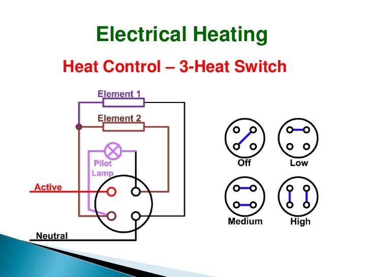
Electrical Heating

Help with heater wiring - 3-way switch to a contactor - DIY Electric Car Forums
Simple Danfoss 3 Way Valve Wiring Diagram UK DIY FAQ Electrical And Mid Position | Heating systems

3 Phase Immersion Heater Wiring Diagram Collection

Wiring Diagrams : Stoves Switches and Thermostats : MacSpares | Wholesale spare parts, Supplying
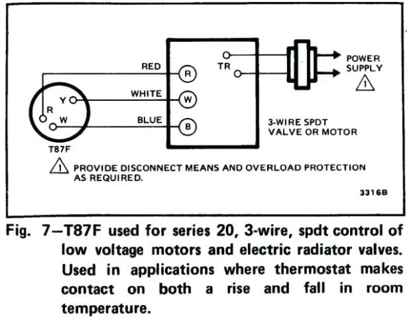
3 Wire Thermostat Heat Only

3 Wire Thermostat Wiring Diagram Hvac - Wiring Diagram Networks

Wiring Diagram For Central Heating

3 Wire Hydronic Zoned Heating Wiring Help? - HVAC - DIY Chatroom Home Improvement Forum
3 Wire Thermostat Wiring Diagram Heat Only / 3 Ton Package Heat Pump Wiring Diag | Wiring
